Product Description
Moto Generator Demonstration Kit
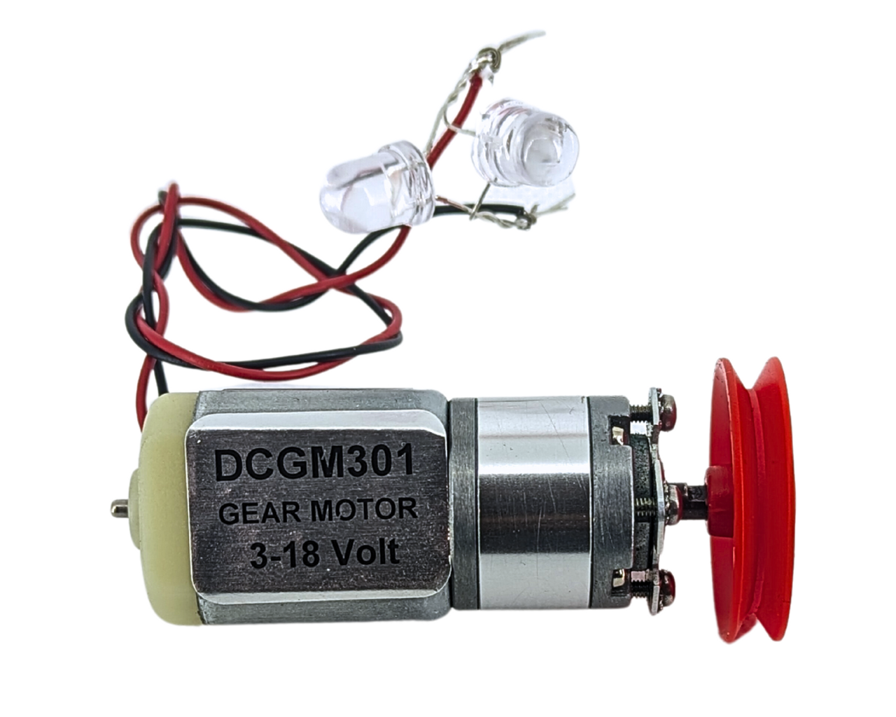
Explore the limitless possibilities of mechanical engineering with our MotoGenerator Demonstration Kit. Equipped with two bright LEDs or Lamp and Light Bulb, a high-performance REFURBISHED Planetary Gear Motor, and an exceptional Speed Reduction Mechanism, along with a 30mm red plastic pulley, this kit is perfect for students, hobbyists, and DIY enthusiasts alike.
Discover the magic of motion as gears mesh and pulleys spin, and witness the transformation of energy right before your eyes. The innovative Speed Reduction Mechanism allows you to effortlessly switch between two modes: when used as a motor, it provides high torque and low speed, and when used for electricity generation, it delivers high speed in response to your torque, making electric generation a breeze! Whether you're seeking powerful motor performance or generating electricity with ease, this kit empowers you to achieve both!
Key Features:
- REFURBISHED Planetary Gear Motor
- Speed Reduction Mechanism
- 30mm Red Plastic Pulley
- Two Bright LEDs or Lamp and Light Bulb
- Transforming Energy
- High Speed and Low Torque
- Effortless Electricity Generation
Product Specifications:
| Specification | Details |
| Motor Type | Planetary Gear Motor |
| Pulley Size | 30mm |
| Light Source | Two Bright LEDs or Lamp and Light Bulb |
| Mode | Motor / Electricity Generation |
Similar Products:
- Motion Generator Science Kit
- Engineering Wonder Gear Set
- DIY Electricity Generation Kit
- Creative Mechanical Engineering Set
- Hands-On Gears and Pulleys Kit
Note: These are similar products, and each product is different, so research is required to find the best fit for your needs.
Perfect for students, hobbyists, and DIY enthusiasts interested in mechanical engineering and hands-on learning.
Circuit Setup: LEDs
Step 1: Identify LED Polarity
LEDs have two leads: the anode (+) and the cathode (-). The anode is typically the longer lead, and the cathode is the shorter lead. Additionally, the cathode may have a flat edge or a notch on the LED body.
Step 2: Connect the LEDs in pairs
Take the first LED and identify its cathode (-) and anode (+) leads based on the characteristics mentioned in Step 1.
Take the second LED and similarly identify its cathode and anode leads.
Now, connect the cathode of the first LED to the anode of the second LED, and the same in viceversa. This creates a pair of LEDs with their cathodes and anodes connected together.
Step 3: Connect LED pairs to the generator
With the LED pairs properly connected, you can now connect one pair (cathode-to-anode connection) to one of the generator's output wires. Attach the cathode end of the pair to one output wire of the generator.
Connect the other pair of (cathode-to-anode connection) to the other output wire of the generator.
Step 4: Spin the generator
Now, as you spin the generator, it will generate electricity. The generated electricity will flow through the LED pairs, lighting up one LED when you spin the generator in one direction and the other LED when you spin the generator in the opposite direction.
Explanation:
LEDs, being diodes, are polarized components. This means that they only allow current to flow in one direction, from the anode (+) to the cathode (-). Therefore, it is essential to connect the LEDs in the correct orientation to ensure they function as intended.
By identifying the cathode and anode leads of each LED, you can connect them properly in pairs. When you connect the LED pairs to the generator and spin it, the generator will generate an electric current. Depending on the direction of rotation, the polarity of the generated current will change. As a result, the current will flow through the LED pairs in different directions, lighting up one LED when the generator spins in one direction and the other LED when it spins in the opposite direction.
This setup provides a visual representation of how the direction of rotation of the generator affects the polarity of the generated electricity, resulting in the lighting of one LED or the other.


